
Comparator Chart Engineering

Introduction
After Pearl Harbor, the USA had to rev-up quickly to fight in World War II. Optical gaging was instrumental in helping the war effort by permitting the manufacturing of parts in record time. It offered a way to guarantee interchangeable in manufacturing. This was a major problem at the time. By using optical gaging, it could be guaranteed that a screw manufactured on the west coast would fit a tapped hole manufactured on the east coast. It could also be guaranteed that vendors in various parts of the USA would produce parts within tolerance. This was accomplished by the customer sending duplicate chart-gages to his vendors.
The chart-gages contained lines, which represented the tolerance limits of the parts. The Chart-Gages were used on optical comparators. The shadow of the part had to be within the tolerance zones on the Chart-Gage to be acceptable. It would be allowed to leave a vendor’s plant only if it met this criterion.
Today, there are many ways to guarantee interchangeable and uniformity. However, optical gaging is often overlooked. If the engineer or manufacturer does not consider optical gaging in the control quality, he or she can be missing an opportunity to accomplish an inspection quickly, economically, and accurately, using lower labor grade employees. The part form can be seen at magnification and examined. Tangent points can be studied. Very small radii and other features can be easily checked when enlarged on the screen. These are a few reasons for considering optical gaging.
Once a person becomes familiar with optical gaging he or she will use it more often. Quick measurements can be made using standard or custom Chart-Gages. Using a custom gage guarantees that each operator will accept parts to the same standard each time. Whether checking one or a thousand part, today or a year from now, the results will be the same.
Optical Gaging
With the great variety of new gaging equipment on the market, an easy and practical approach is sometimes overlooked. Many are discovering that inspection with the use of an Optical Comparator, a custom Chart-Gage and a Staging Fixture or a Tracer is economical and requires little experience. This approach has provided a simple solution to some difficult gaging problems. Gage-Line Technology has 55 years experience in optical gaging. We just require some basic information from our customer and we do the rest.
The following information helps us give our customers exactly what they need to solve their gaging problem:


- A statement of the gaging problem or dimensions to be inspected-
- A part print, sketch, or CAD file-
- Locating surfaces on part identified-
- Number of parts to be inspected-
- Inspection rate-
- Is fixturing or staging required-
- Model and make of comparator-
- Magnifications available-
- Is surface illumination available-
Chart-Gages
The chart-gage is a gage and it must be treated as such. The following considerations are important:
- It should be made of a dimensionally stable material. Rigid material is preferred.
- The humidity and temperature coefficients must be considered.
- The lines on the chart-gage must be uniform in width with sharp edges.
- The lines must withstand normal usage and cleaning.
- They should be stored flat (never rolled) in a normal gage room environment.
- They should be calibrated at intervals determined by the usage.
- The Chart-Gage Master image should be produced with a precision plotter to .001” or better accuracy.
- The final chart-gage should be accurate to ±.002 or 10% of the part tolerance times
the magnification used, which ever is greater. - Calibration fiduciary marks should be included for dimensional control.
Custom Optical & Digital Chart-Gages:
We have over 60 years of experience in chart-gage and we will put this experience to work for you. A CAD file or a marked-up print along with the chart size and magnification is all that is usually required for us to price your custom Chart-Gage.


Standard Chart-Gages:
Gage-Line chart-gages are of the highest quality in the industry. They are reproduced under controlled conditions from precision master on to selected dimensional stable plastic or selected soda lime glass.
Standard Chart-Gages Are available with various line patterns at various magnifications in English or Metric.


")


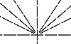
Centerline Chart-Gage: A basic glass Chart-Gage for comparators.
 (PDF - 591kb)
 (PDF - 650kb)
 (PDF - 724kb)
 (PDF - 29kb)
 (PDF - 263kb)
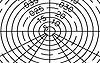
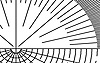
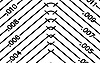
360° Radius Chart-Gage: Shown complete diameters with 30°, 45°, & 60° in two quadrants. All lines are the same width with major lines broken for easy reading.
 (PDF - 564kb)
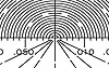
Micro Step Radius Chart-Gage: Used to measure radii in small increment steps. Each 90° or 180° contains radii segments that are stepped-up one increment from each other, therefore, making it easy to read radii in small increments.
 (PDF - 480kb)
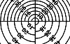
Mulit-Mag Radius Chart-Gage: Radii are shown at 10x, 20x, 50x, and 100x over 360°.
 (PDF - 420kb)
Macro Radius Chart-Gage: Used for checking large radii with centers outside the screen area. Radii are marked with the actual size of the radii on the chart-gage; therefore, they can be used at any magnification including same size. Just divide the value of the radius measured on the chart-gage by the magnification to arrive at the value of the radius on the part.
Grid Chart-Gage:
 (PDF - 326kb)
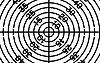
Grid Chart-gage: Very useful gage, that provides a quick way of making measurements on the screen without the use of projector table measurement devises. It is also used for centralizing holes rapidly, for checking tapers/inch, for checking layouts by laying over grid, for making temporary layouts, and for taking photographs of the shadow and grid simultaneously for record purposes.
Protractor Chart-Gage:
 (PDF - 67kb)
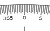
Protractor Centerline Chart-gage: The protractor is shown at the perimeter of the chart-gage. This gage provides a means to measure angles quickly and accurately. Especially valuable on projectors which are not equipped with angle measuring. Angle increments are 10 minutes (0° 10’). Can be use with any magnification.
 (PDF - 279kb)
Protractor Combination Chart-Gage: Any standard or custom chart-gage can be printed on a protractor centerline chart-gage.
Combination Chart-Gage:
 (PDF - 488kb)
Tool Room Chart-Gage: A universal gage, which combines grid, radii and angle lines to make optical inspection simpler. The tool-room chart-gage is a worthwhile addition to any projector, with out measuring attachments.
 (PDF - 306kb)
Radius Angle Chart-Gage: A versatile gage that is used to check fillets, chamfers, threads, holes, point in space.
 (PDF - 281kb)
Radius, Angle, Scale Chart-Gage: A versatile gage that is used to check fillets, chamfers, threads, holes, point in space and measurements along angles.
Thread Chart-Gage:
Thread Chart-gage: Gage-Line has many standard thread chart-gages available than are not listed and will recommend a suitable gage on request. The following information is required:

(PDF – 50kb)
- Size and description of thread?
- Standard thread specifications to be used?
- What features are to be inspected?
- Staging normal to axis or to helix?
- Projector: make and model?
- Magnification available?
- Plastic or glass chart-gage?
Blanks: A blank chart material used for making charts and other uses.
 (PDF - 16kb)
Ground Glass: Selected soda lime flat glass with one side clear and the other side fine ground suitable for precision imaging. Precision ground diameters available in .125” & .250” nominal thickness.
 (PDF - 16kb)
Clear Rigid Plastic: An optical clear plastic in various thickness and diameters.
Disc-Gages:
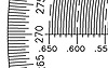
The Disc- Gages are handheld against the comparator screen and aligned over the image of a radius to measure it. They are especially helpful when measuring small radii that are not practical to inspect on a CMM or by other means. They may also be used at “one to one” by overlaying on a part.
Will answer questions such as:
- Is the size right?
- Is it a true radius?
- Is radius tangent?
- Are burrs present?
Use Disc-Gages to:
- Gather variable data to determine radii on prototypes.
- Confirm program and tooling for CNC equipment.
- Inspect small diameter holes.
- Inspect internal radii by sectioning part, making a mold
or by using a Gage-Line Contour Tracer.
Three styles are available.
 (PDF - 113kb)
 (PDF - 141kb)
 (PDF - 44kb)
The Disc-Gages are diameter 6” x .05 thick with a laminated protected image. They are available at various magnifications including actual size in Metric or English. Actual size can be used as sight gages to inspect castings, rubber parts, printed circuits, photo-chemically milled parts and, other uses.
Lines are either black or translucent amber. Custom Disc-Gages can be made with a white line.
The Disc-Gages contain fiduciary lines for easy calibration and are traceable to N.I.S.T.
Disc-Gages can be customized to suit customer’s needs.
Pocket Comparators with 6x or 10x magnifications containing Disc-Gages with various colored lines for use directly on the part are also available.
 | 270 DEGREE (PDF - 113kb) |
|||
| CAT. NO. | MAG. | SCALE | RANGE | INCR. |
| 100579 | 1X | INCH | 0.05 - 2.50 | 0.05 |
| 100580 | 1X | INCH | 0.04 - 2.60 | 0.05 |
| 100581 | 1X | MM | 1 - 64 | 1.0 |
| 100582 | 1X | MM | 1 - 64 | 2.0 |
| 100541 | 10X | INCH | 0.005 - 0.250 | 0.005 |
| 100576 | 10X | MM | 0.1 - 6.4 | 0.1 |
| 100542 | 20X | INCH | 0.002 - 0.126 | 0.002 |
| 100577 | 20X | MM | 0.05 - 3.20 | 0.05 |
| 100543* | 31.25 | INCH | 0.001 - 0.080 | 0.001 |
| 100544* | 31.25 | MM | 0.02 - 2.00 | 0.02 |
| 100549 | 50X | INCH | 0.001 - 0.050 | 0.001 |
| 100578 | 50X | MM | 0.02 - 1.28 | 0.02 |
| 100546* | 62.5 | INCH | 0.0005 - .040 | .0005 |
| 100547* | 62.5 | MM | 0.01 - 1.00 | 0.01 |
| 100545 | 100X | INCH | 0.0005 - 0.025 | 0.0005 |
| 100550 | 100X | MM | 0.01 - 0.64 | 0.01 |
| 360 DEGREE (PDF - 141kb) |
|||
| CAT. NO. | MAG. | SCALE | RANGE | INCR. |
| 100561 | 10X | INCH | 0.005 - 0.250 | 0.005 |
| 100570 | 10X | MM | 0.1 - 6.4 | 0.1 |
| 100548 | 20X | INCH | 0.002 - 0.126 | 0.002 |
| 100409 | 20X | MM | 0.05 - 3.20 | 0.05 |
| 100562 | 20X | INCH | 0.005 - 0.125 | 0.005 |
| 100565 | 20X | MM | 0.1 - 3.2 | 0.1 |
| 100410* | 31.25 | INCH | 0.001 - .080 | 0.001 |
| 100411* | 31.25 | MM | 0.02 - 2.00 | 0.02 |
| 100563 | 50X | INCH | 0.001 - 0.050 | 0.001 |
| 100571 | 50X | MM | 0.02 - 1.28 | 0.02 |
| 100412* | 62.5 | INCH | 0.0005 - .040 | 0.0005 |
| 100413* | 62.5 | MM | 0.01 - 1.00 | 0.01 |
| 100414 | 100X | INCH | 0.0005 - 0.025 | 0.0005 |
| 100415 | 100X | MM | 0.01 - 0.64 | 0.01 |
 | 90 DEGREE CORNER RADIUS (PDF - 44kb) |
|||
| CAT. NO. | MAG. | SCALE | RANGE | INCR. |
| 100551 | 10X | INCH | 0.001 - 0.025 | 0.001 |
| 100556 | 10X | INCH | 0.025 - 0.050 | 0.001 |
| 100574 | 10X | MM | 0.025 - 0.625 | 0.025 |
| 100575 | 10X | MM | 0.625 - 1.250 | 0.025 |
| 100552 | 20X | INCH | 0.001 - 0.025 | 0.001 |
| 100557 | 20X | INCH | 0.025 - 0.050 | 0.001 |
| 100566 | 20X | MM | 0.025 - 0.625 | 0.025 |
| 100567 | 20X | MM | 0.625 - 1.250 | 0.025 |
| 100553* | 31.25 | INCH | 0.001 - 0.025 | 0.001 |
| 100558* | 31.25 | MM | 0.025 - 0.625 | 0.025 |
| 100554 | 50X | INCH | 0.001 - 0.025 | 0.001 |
| 100559 | 50X | INCH | 0.025 - 0.050 | 0.001 |
| 100572 | 50X | MM | 0.025 - 0.625 | 0.025 |
| 100573 | 50X | MM | 0.625 - 1.250 | 0.025 |
| 100416* | 62.5 | INCH | 0.001 - 0.025 | 0.001 |
| 100417* | 62.5 | MM | 0.025 - 0.625 | 0.025 |
| 100555 | 100X | INCH | 0.001 - 0.025 | 0.001 |
| 100560 | 100X | MM | 0.025 - 0.625 | 0.025 |
Comparator Calibration
The Gage-Line ® Calibration and Inspection Kit provides the capability to check the accuracy or to calibrate instruments, machines, layouts, comparators, and other similar systems. All artifacts are chrome line on selected soda lime glass. Artifacts are available A2LA certified, traceable to N.I.S.T. or uncalibrated.
Comparator Calibration Kits:

- Glass 12” Calibration Scale
- Glass 22” Calibration Scale
- Plastic 12” Multi-Mag Scale
- Glass Magnification Check Scale
- Glass Magnification Check Reticle
- Glass Angle Scale
- Grid
- Staging Fixture
- 6x Magnifiers
- Eye Loupe Magnifier

Eye Loupe Magnifier
(PDF – 660kb)
Accessories
Comparator Staging Fixtures
Used to conveniently stage or hold parts on a comparator. it can also be used as base for additional fixturing. When the fixture is inserted in the key way, it is automatically squared and held in place with a spring-loaded knob. The champing faces are Teflon and an elevating adjustment is provided. This makes it an ideal fixture for holding and squaring glass Calibration Scales and Grids.
Although made for use on a horizontal comparator, the fixture can be adapted for use on a vertical comparator.
The fixtures are usually sold in pairs and marked left hand Cat. No. 100335 and right hand Cat. No. 100334. Adjustments are easier when using both fixtures. (Cat. 100759 Includes both Left and Right)

Staging Fixtures (Cat. No. 100334 shown)
(PDF – 660kb)
Contour Tracer
The Gage-Line Tracer makes it possible to inspect contours that are normally difficult to check by standard methods. These contours include internal features, depressions, recesses and cross-sections.
The tracer is a manual device that is staged in the keyway slots on the table of a horizontal optical comparator. The tracer has two probes which travel simultaneously to each other. One probe (tracer probe) is used to trace the part while the image of the other probe (follower probe) is projected on the comparator screen.
The follower probe copies the motion of the tracer probe. The inspection is made with the aid of a custom comparator chart-gage, grid chart-gage, scale, or a digital readout.
The measuring versatility of the Gage-Line Tracer with its multi-position probe allows measurement of a great variety of parts. When used with glass Reticle-Gages or multiple followers, the Gage-Line Tracer can be customized for specific applications requiring extended areas beyond the normal viewing area of the comparator.
The counter balance “feather touch” movement provides for fast, precise inspection without marring most work surfaces.
The Tracer can be made to interface with a direct readout or computer.

Standard Contour TRACER
(PDF – 338kb)

Probe Image on Screen
(PDF – 341kb)
")
Custom Tracer (Comparator not required)
(PDF – 88kb)